This comprehensive guide covers every critical stage of window and door installation using standard frame connecting plates. From initial cleat adjustment to final sealant curing, follow these step‑by‑step instructions to ensure structural integrity, thermal performance, and long‑lasting durability. All references to figures correspond to the technical diagrams in the original manual.
1. Standard Frame Cleat Installation & Initial Positioning
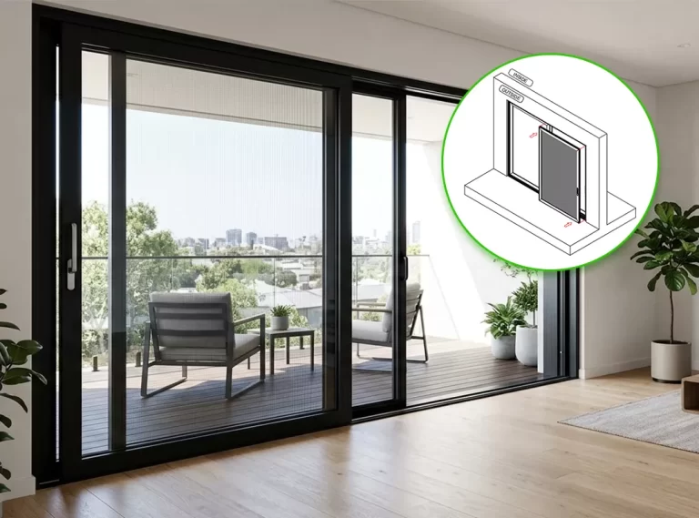
Refer to diagrams on the right for standard frame cleat installation. Follow these precise actions:
- Adjust the cleat from a parallel to a vertical position.
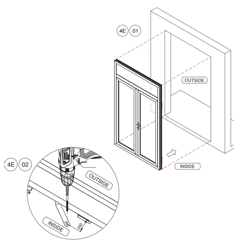
- Install the window/door carefully into the wall opening from the interior toward the exterior.
- Align with interior/exterior reference lines – these lines must guarantee that the distance between the screw and the wall edge is at least 50 mm (1.97″).
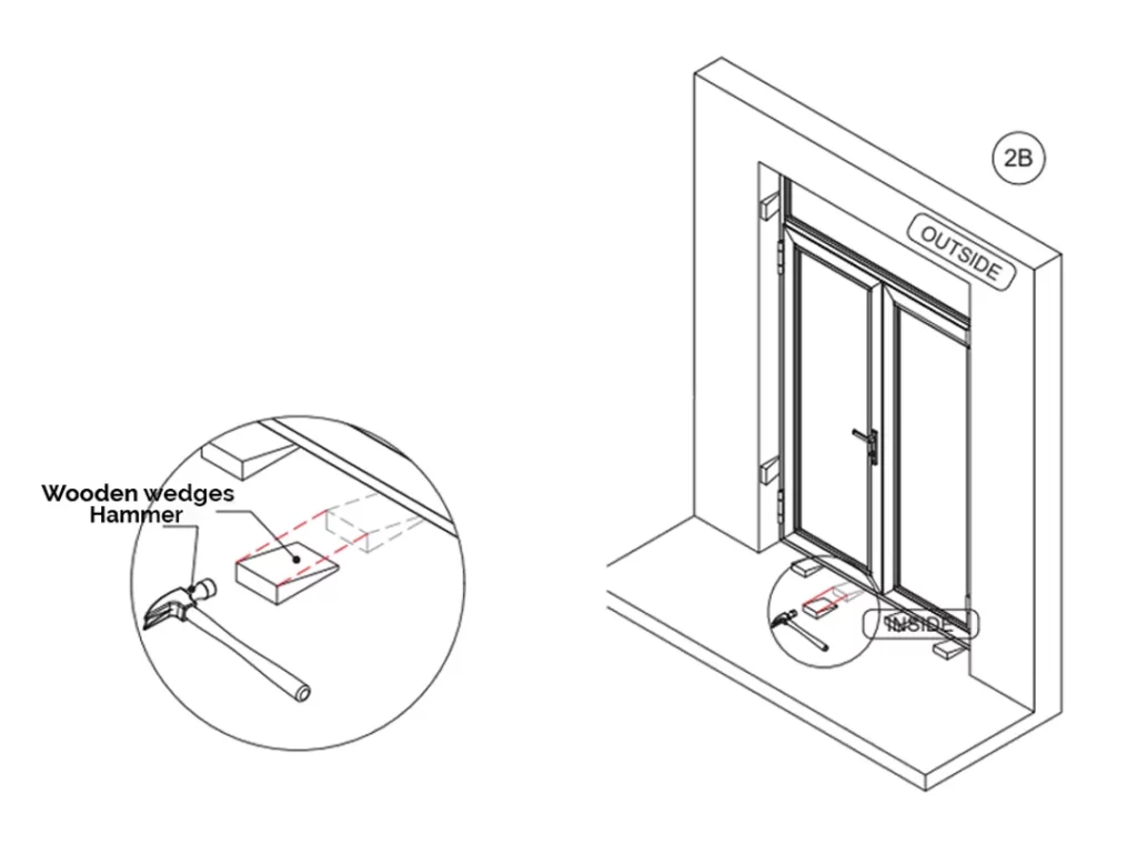
2. Adjusting Gaps Between Frame and Wall Opening
See Figure 2B From the interior side, carefully adjust the gap between the horizontal/vertical frames and the wall opening.
- Use tools such as wooden wedges or adjustment tools to achieve uniform gaps on all sides.
- Ensure consistent spacing to facilitate later sealing and structural performance.
3. Spirit Level Check – Vertical & Horizontal Alignment
Use a spirit level to verify the vertical and horizontal alignment of the installed window/door. If any deviation is detected:
- Repeat the gap adjustment procedure (step 2) until the frame is perfectly plumb and level.
Refer to the figure on the right for correct level placement.
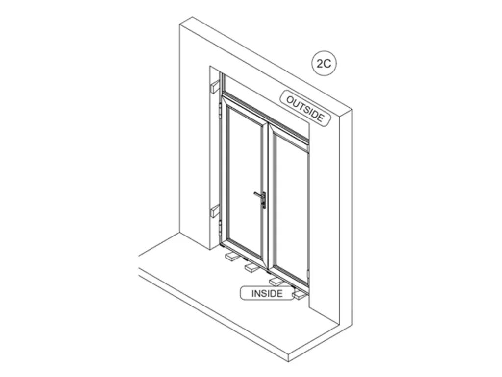
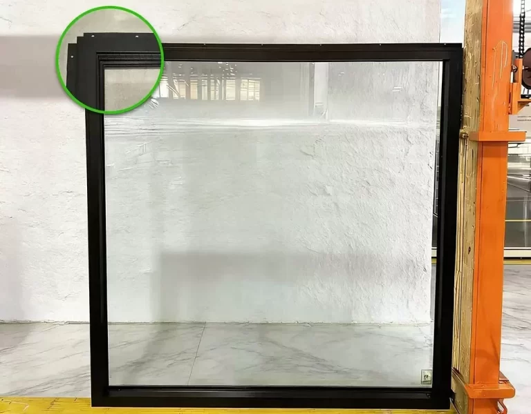
4. Setting Blocks: Positioning, Materials & Load‑Bearing Rules
Setting blocks are essential for load distribution and frame stability. Follow these specifications:
(1) Classification: They are divided into support blocks (load‑bearing) and positioning blocks (non‑load‑bearing).
(2)Material: Must be made of hard, thermal‑insulating, and corrosion‑resistant flat material. Combine thicknesses (25/64″, 13/64″, 1/8″, 1/16″) to achieve the required total thickness.
(3)Flush placement: Blocks should be flush with the inner surface of the frame and must not protrude.
(4)Optimal location: Ideally placed near the screws that connect the cleat to the frame.
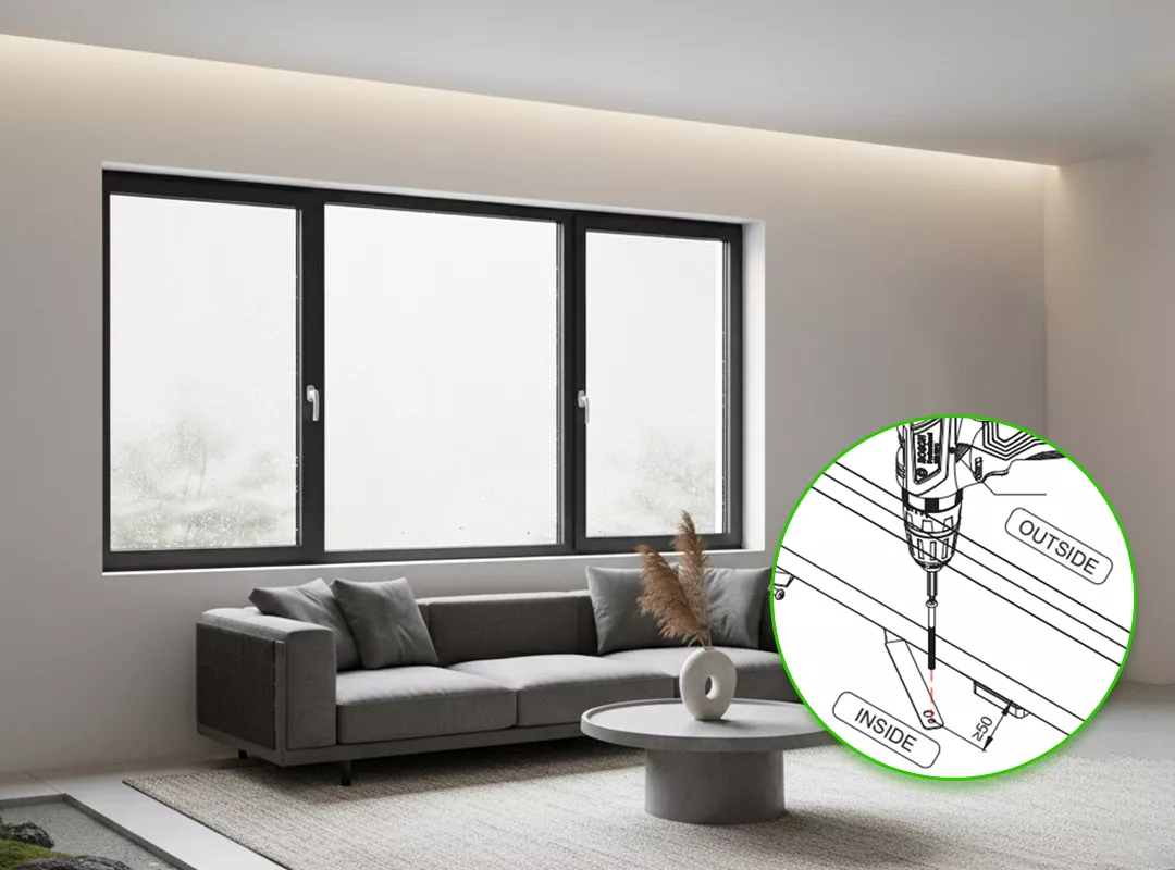
5. Cleat Positioning, Spacing & Fixing Sequence
See right picture for spacing details Adjust the cleat from vertical to a specific angle if needed. Critical requirements:
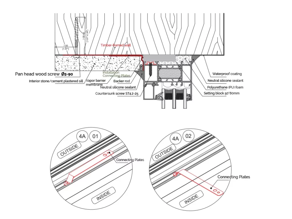
- Ensure screw holes for cleat‑to‑wall installation are more than 50 mm (19.7″) from the wall surface.
- For timber‑framed walls, use ∅5‑90 wood screws.
(1) Factory pre‑fixing & screw options
- All cleats must be pre‑fixed in the factory.
- Optional screws: Torx flange head self‑tapping screws (ST7.5 × 102) can be selected as required.
(2) Installation sequence
- Fix the four corner cleats first, then proceed with the others.
- If the gap between cleat and wall is too large, use pliers to bend the cleat until it sits flush against the wall opening.
- For positions on both sides and the top where setting blocks are not installed, wooden wedges or similar temporary retainers should be kept in place until later steps.
6. Interior Vapor Barrier Membrane – Application & Detailing
After removing temporary fixtures (e.g., wooden wedges) from the interior side, keep support and positioning setting blocks in place. Apply the interior vapor barrier membrane as shown in Figure 2K. Additional instructions:
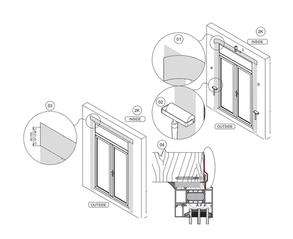
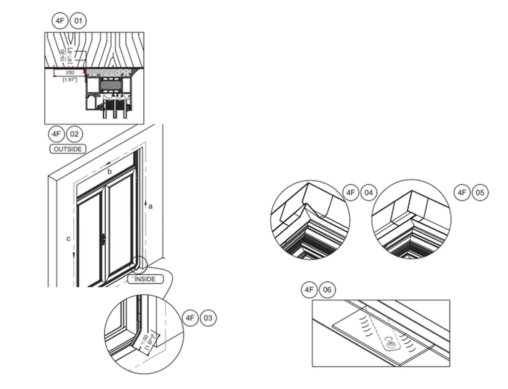
(1)Expansion allowance: During bonding, reserve an allowance (see Figure 4F‑01) to prevent tearing due to potential wall‑to‑window movement. Bonding width on the frame surface must be at least 19/32″.
(2)Bonding sequence: Start from the middle of the side and proceed toward the bottom of the frame (sequence a → b → c as in Figure 4F‑02).
(3)Corner overlaps: Reserve extra tape and fold it to create an overlapped bond (Figures 4F‑04 & 4F‑05).
(4)Cleat exposure: Any exposed areas at the installation cleats must be patched with cut pieces to ensure full coverage (Figure 4F‑06). The membrane at the four corners must have no gaps that penetrate from inside to outside.
7. Exterior Polyurethane (PU) Foam Application
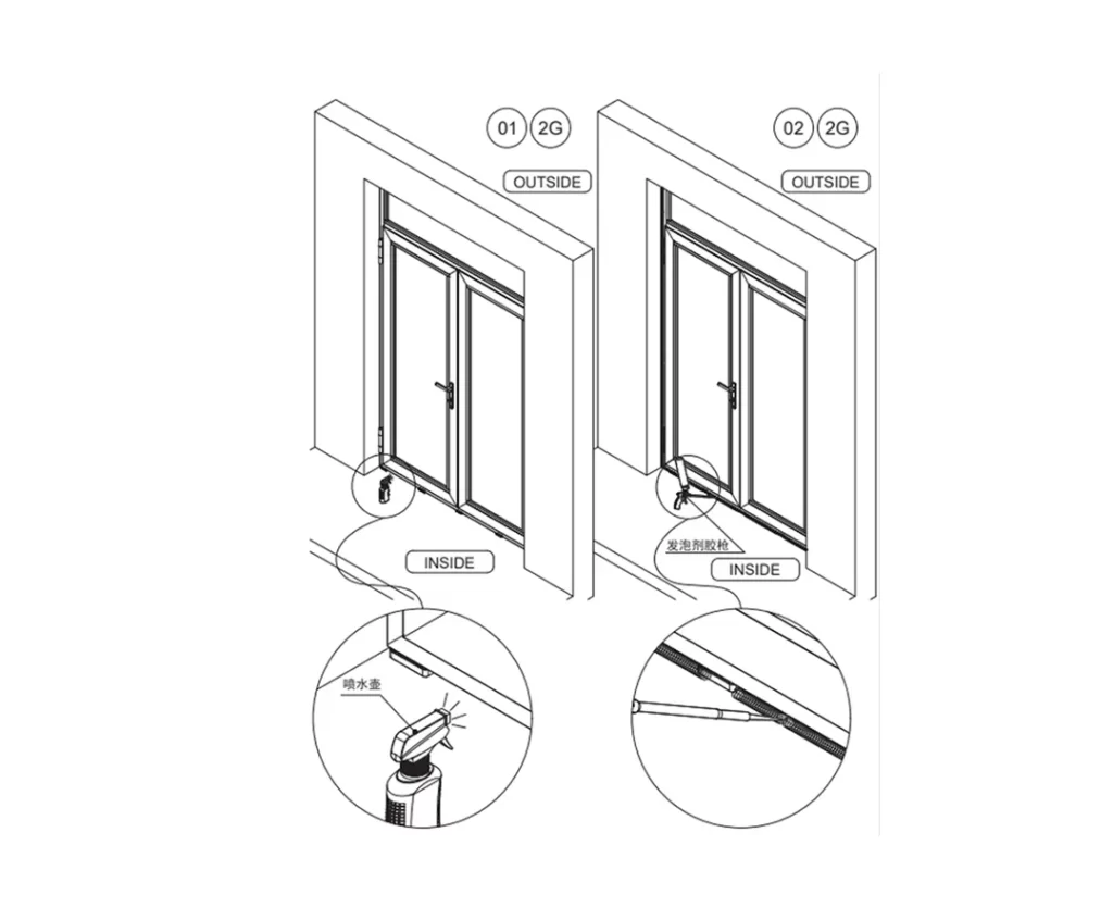
After the vapor barrier is bonded, apply PU foam from the exterior side. Lightly spray water into the gap between window frame and wall (Figure 2G) to improve foaming and shorten curing time. Operating instructions:
- Foam must be applied continuously and fill the entire gap firmly – no voids or omissions.
- Do not press down on overflowing foam with hands or tools after expansion.
- Do not perform any work until foam is fully cured (typically 20–30 minutes; extend this time in lower winter temperatures).
8. Foam Trimming After Curing
Once foam is fully cured, trim the excess with a utility knife. Precautions:
- Ensure the cut is flat and smooth; be careful not to scratch the window frame.
- After trimming, inspect the cross‑section – it must be continuous and full. Repair any gaps immediately.
- Clean up all trimmed foam waste from the opening.
9. Exterior Sealant Application – Step‑by‑Step
Apply sealant to the exterior side of the window. Follow this method for a professional finish:
(1)Clean the application area thoroughly, removing dust and foam debris.
(2)Set the joint width based on site conditions and apply masking tape for a neat, aesthetic finish.
(3)Squeeze the caulking gun smoothly at a 45° angle to seal the gaps.
(4)After application, carefully remove the masking tape (if used).
(5)Do not touch the sealant for at least 3 hours (initial set); it will fully cure after 24 hours.
10. Finishing Details: Exterior Insulation & Interior Cladding
(1)Exterior wall insulation layer
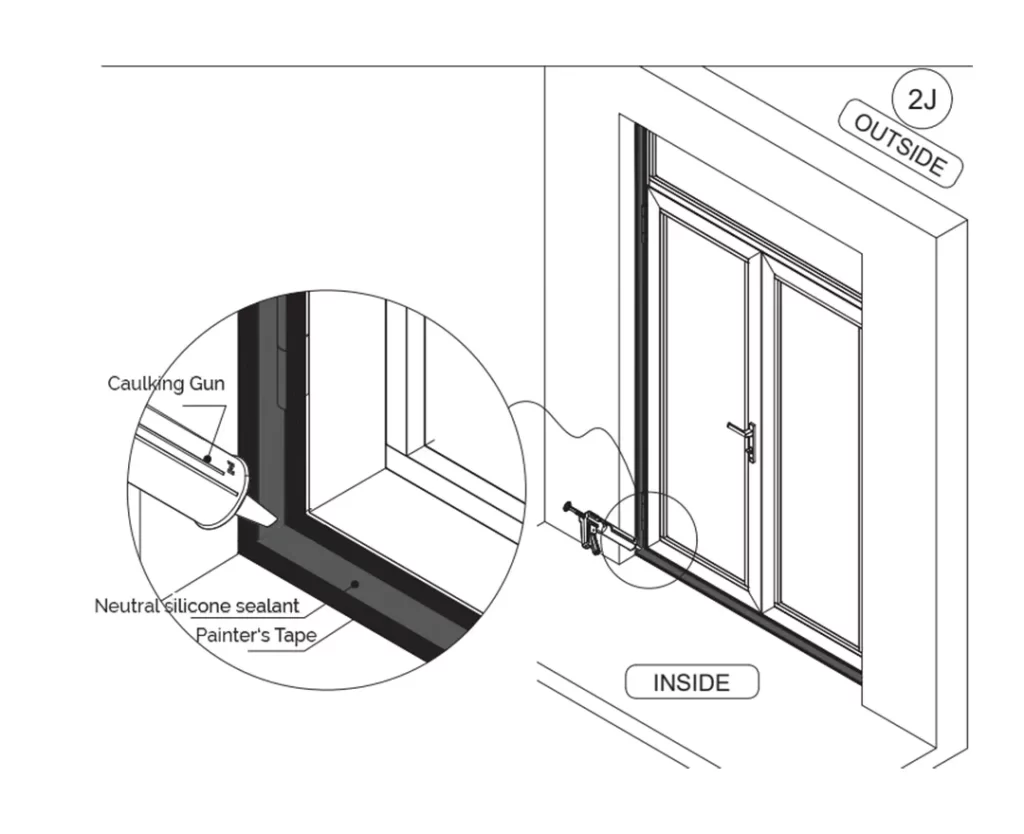
A gap of approximately 25/64″ should be reserved between the window frame and the insulation layer. Insert a foam backer rod before applying sealant (see 2J for sealant application method)
(2)Interior finishing
Interior finishing may use stone, cement, or other materials depending on project requirements. Finishing methods will vary accordingly; always follow material‑specific guidelines.