
1.Refer to the diagram on the right for the installation of the window/door nailing fins.
Horizontally install the unit into the rough opening from the exterior toward the interior; do not drive screws into the nailing fins yet.

2.See Figure right for illustration
From the interior, adjust the gap between the horizontal/vertical frames and the wall opening; Ensure uniform gaps on all sides using tools such as wooden wedges or adjustment tools;

3.See Figure right for illustration
Use a spirit level to check the vertical and horizontal alignment of the window/door; See Figure right for illustration If there are deviations, repeat step B until alignment is correct;

4.Installation, positioning, and instructions for setting blocks:
- 1.Setting blocks are classified into support blocks and positioning blocks based on load-bearing requirements;
- 2. Setting blocks must be made of hard, thermal-insulating, and corrosion-resistant flat material; Combine different thicknesses (25/64″,13/64″,1/8″,1/16″) to achieve the required total thickness;
- 3. The blocks should be flush with the inner surface of the frame and not protrude;
- 4. See 2D-02 for installation position instructions.

5.See Figure right for illustration
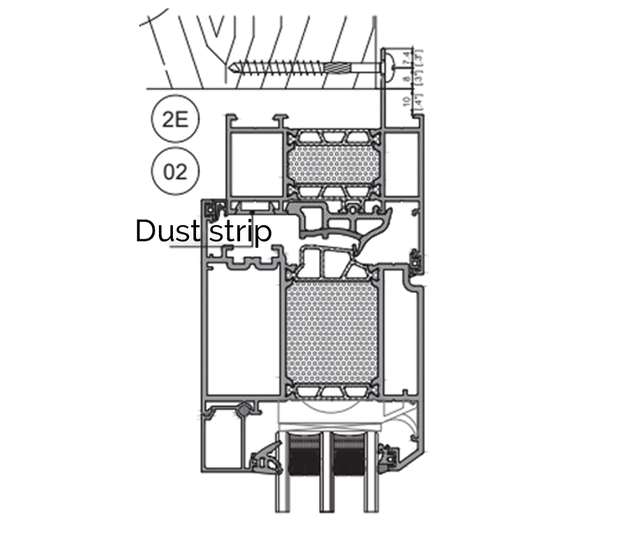
Drive installation screws from the exterior side through the pre-drilled holes on the nailing fins. For wooden walls, φ5*90 pan-head wood screws are recommended.
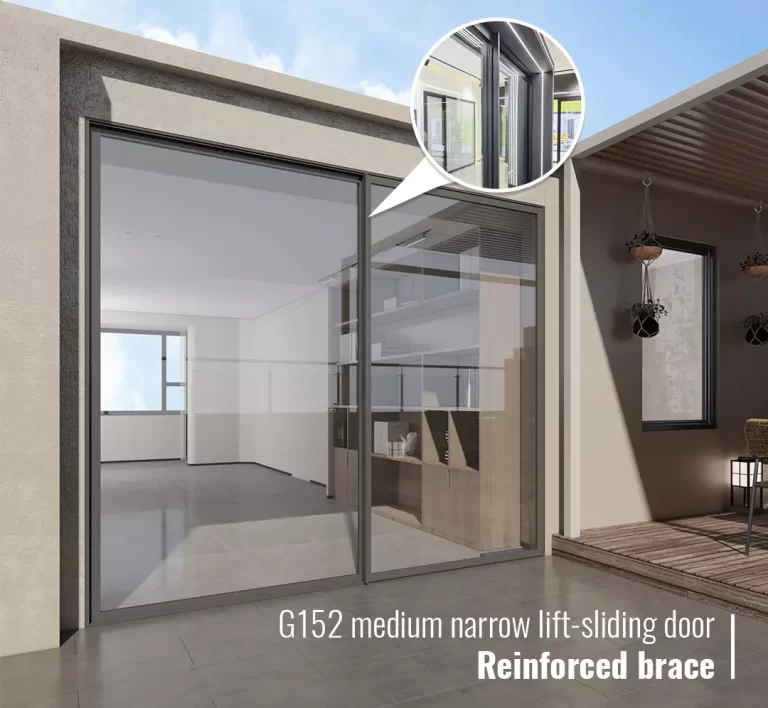
2. On the top, left, and right sides of the opening sash, the installation holes must be covered with dust-proof rubber strips after the screws are secured.
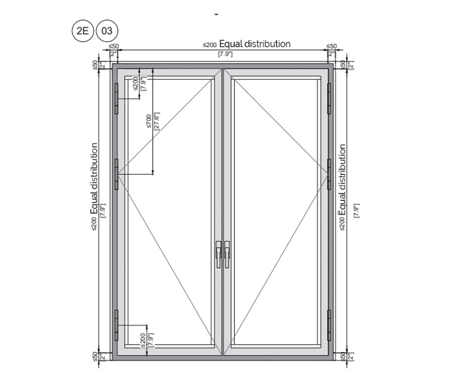
Installation Position Instructions for Setting Blocks
1. The lower installation positions for support setting blocks are at the two corners and below the mullion. Other blocks should be distributed evenly at intervals of ≤500mm (19.7″).
2.When installing screws or connecting plates, the setting blocks should be positioned 150–200mm (5.9″–7.9″) to the left or right of the installation holes.
3.Vertical positioning blocks are located at the corners on the hinge side and at the corresponding diagonal positions.
4.Do not install setting blocks on the top side.
5.Setting blocks on both sides must be bonded firmly and must not fall off (if necessary, a suitable amount of polyurethane foam adhesive can be applied to the underside of the block for fixation).
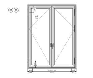
Sill Installation Hole Distribution Diagram
1. The distance from the fastening points to the corners is 150mm (5.9″), and the center-to-center distance for the remaining parts is distributed evenly at ≤ 500mm (19.7″), as shown in the figure above.
2.All sill (bottom threshold) solutions shall follow the above installation hole distribution rules.

6.Remove
Remove temporary fixtures such as wooden wedges from the interior side, while keeping the support and positioning setting blocks in place
7.Polyurethane (PU) Foam Application
After the vapor barrier membrane is bonded, apply PU foam from the exterior. Lightly spray water into the gap between the window frame and the wall (see Figure 2G) to improve the foaming effect and shorten the curing time;
Operating instructions are as follows:
(1) The foam must be applied continuously and fill the entire gap firmly, without any voids or omissions;
(2) Do not press down on the overflowing foam with hands or tools after expansion;
(3) Do not perform any operations until the foam is fully cured (usually 20-30 minutes; extend this time in lower winter temperatures);

8.Foam Trimming
Once the foam is fully cured, trim the excess with a utility knife.
(2)After trimming, inspect the cross-section to ensure it is continuous and full. Check for any gaps and repair if necessary;
(3)After completing the above operations, clean up the trimmed foam waste from the opening;
9.Exterior Sealant Application
Apply sealant to the exterior side of the window.
The method is as follows:
(1) Thoroughly clean the application area, removing dust and foam debris
(2) Set the joint width based on site conditions and apply masking tape to ensure a neat and aesthetic finish;
(3) Squeeze the caulking gun smoothly at a 45° angle to seal the gaps;
(4)After application, carefully remove the masking tape. Do not touch the sealant for at least 3 hours (initial set); it will fully cure after 24 hours.
(5)After application, carefully remove the masking tape (can be omitted if not used). Do not touch the sealant for at least 3 hours during initial curing;
(6)The sealant will be fully cured after 24 hours.
10.Waterproof Breathable Membrane Installation
Before adhering the waterproof breathable membrane, apply a layer of waterproof coating first; refer to 1J (Page 09) for details.
The construction method for the membrane is as follows:
(1) While adhering the membrane, peel the release liner as you go. The length peeled at one time should not exceed 500mm (19.7″), and the ambient construction temperature should ideally be above 0°C.
(2) Apply the pre-treated waterproof breathable membrane onto the substrate. Use a rubber roller to press it down during the process to keep the material clean and smooth, avoiding wrinkles and air pockets (pre-reserved deformation is normal). Ensure a tight bond between the membrane and the substrate to guarantee the waterproofing effect.

3) The bonding sequence follows the principle of “left and right first, then the top side” (sequence a-b-c as shown in the diagram). This ensures the overlapping order at the corners follows the direction of water flow, as shown in Figure 01.
4) The overlap amount of the membrane at the corners should be between 80–100mm (3.15″–3.94″), as shown in Figure 03.
(5) When adhering the membrane, an appropriate amount of deformation should be reserved (as shown in Figure 04) to prevent the membrane from tearing due to relative displacement between the window and the wall, which could lead to seal failure.

11.Finishing Details
Instructions for finishing the exterior wall insulation layer with the window/door: A gap of approximately 25/64″ should be reserved between the window frame and the insulation layer. Insert a foam backer rod before applying the sealant;See 2J for sealant application method.